Aluminium die casting guide
Our Aluminium Die Casting design guide provides tips, guidance and best practices for optimising your aluminium die-cast parts.

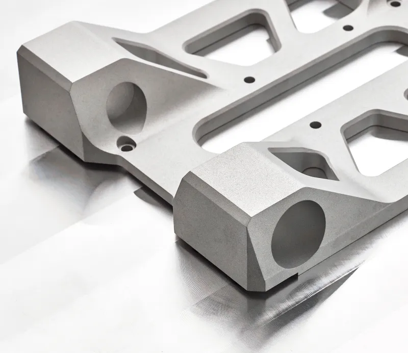
.webp)
The Basics
What is Aluminium Die Casting?
Die casting or aluminium die casting is a high-volume manufacturing process that produces high-accuracy and precision metal parts. The basic principle involves forcing molten metal, at high pressure, into a mould or ‘die’. The metal is then quickly cooled, taking the shape of the die.
The die casting alloys used are optimised for being; lightweight, corrosion-resistant, high thermal/electrical conductivity and have high dimensional stability for complex part geometries.
Many designers prefer the die casting process due to the ability to create high-volume, high-strength, intricate metal parts with precision. Designers often select Aluminium die casting as more cost-effective than alternative casting processes such as sand casting.
{{cta-banner}}
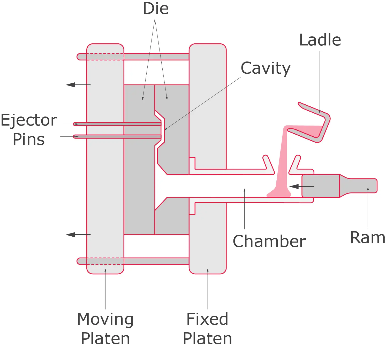
The Aluminium Die Casting process overview
Tool creation
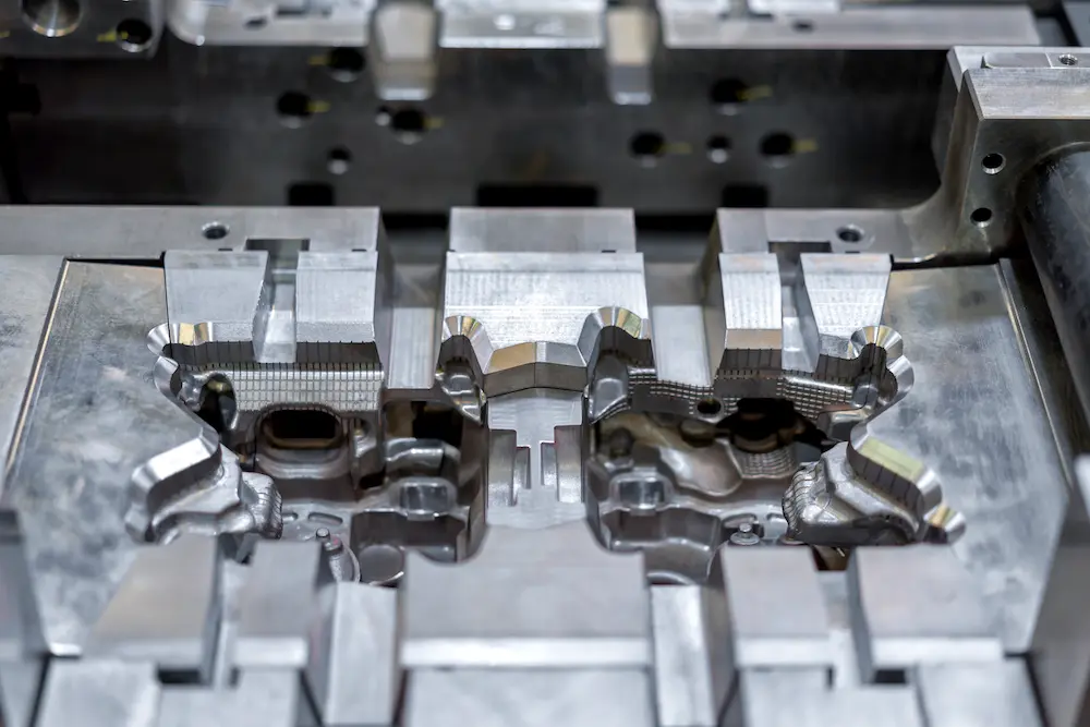
The first step in producing aluminium castings is creating a 3D CAD file. Read our design guidelines below for more information on how best to design your parts for the die casting process. Once you have found a suitable manufacturer and agreed to begin production, the manufacturer will typically be responsible for designing and manufacturing the die. The die generally is CNC machined from hardened tool steel to improve the longevity of the die. A good manufacturer will also carefully consider the mould flow analysis to optimise the tooling for your specific part. The part’s complexity will determine elements such as moveable sliders and cores.
Part production
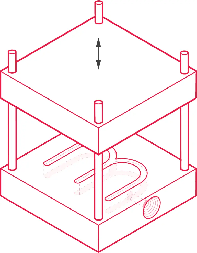
The die-cast cycle begins with two die halves clamped securely together in the die casting machine. The die is arranged so that one half is stationary and the other can be moved perpendicular to the parting plane.
Molten aluminium is then injected into the closed die at high pressure. The amount of metal injected into the die is the shot. The injection pressure is held to ensure that the die continues to fill as the molten material cools and contracts. The injection and hold time required depends on the cast aluminium alloy’s cavity volume, wall thickness, and thermodynamic properties.
Once the part has sufficiently cooled, the die halves are drawn apart, and the casting is ejected using several ejector pins. Due to the soft nature of the warm aluminium, the ejector pins may leave a small imprint on the part's surface. Always work with your manufacturer to determine the best location of possible ejector pin marks.
The die halves are quickly cleaned with compressed air to remove debris and sprayed with a mould release to lubricate the mould before the die closes for the next shot.
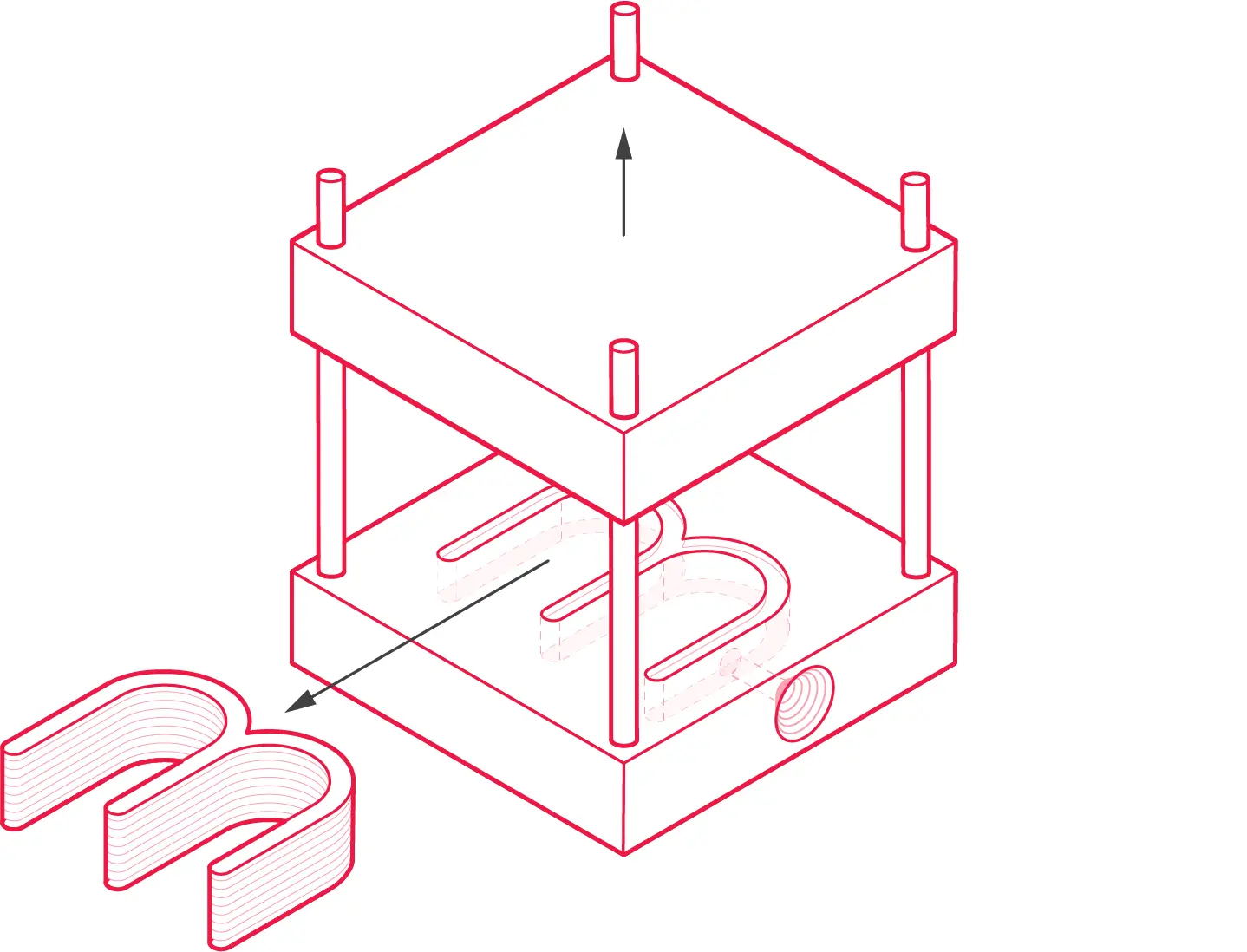
The ejected cast aluminium alloy parts will require trimming to remove the flash, runners and sprues. This is performed either by hand or via a saw or trimming press. Scrap material from the trimming process is either discarded or remelted to be used in future shots.
What are the different types of die casting?
There are two die casting processes: hot chamber die casting and cold chamber die casting. Both methods involve forcing molten metal through a die and allowing it to cool; however, the way the metal is heated differs.
Hot chamber
Hot chamber die casting machines contain a built-in furnace that melts the metal into a molten state before being forced into the die by a high-pressure hydraulic piston. The key difference between hot chamber die casting is that the metal is heated inside the casting machine. It is a relatively fast process with cycle times of around 20 minutes. This process is best suited for metals with a lower melting temperature, such as; zinc alloys, magnesium alloys and lead alloys.
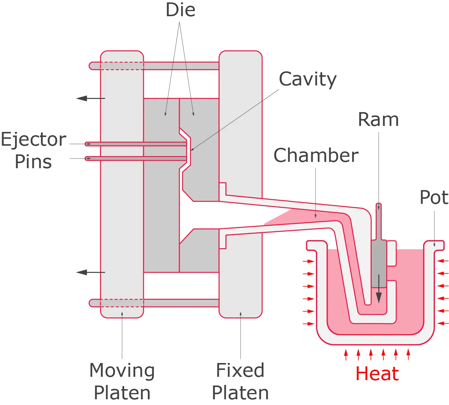
Cold chamber
Cold chamber die casting works similarly to hot chamber die casting; metal is heated into molten metal and then forced into a die under high pressure using a plunger. However, cold chamber die casting is different because the metal is heated in an external furnace and then transferred to the casting machine by a ladle or transfer tube in a molten state. This process is used when casting with higher melting point metals such as; aluminium, brass and copper. The external furnace must heat the metal to a high enough temperature to be turned into a molten state. The cycle times are longer due to the extra step in transferring the molten metal.
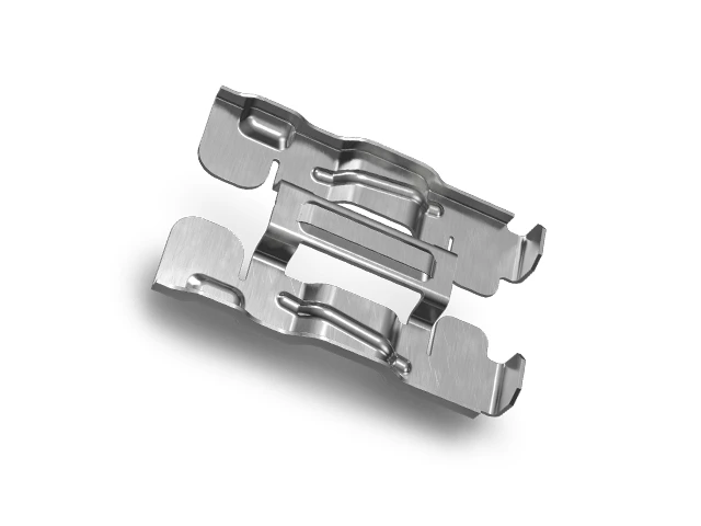
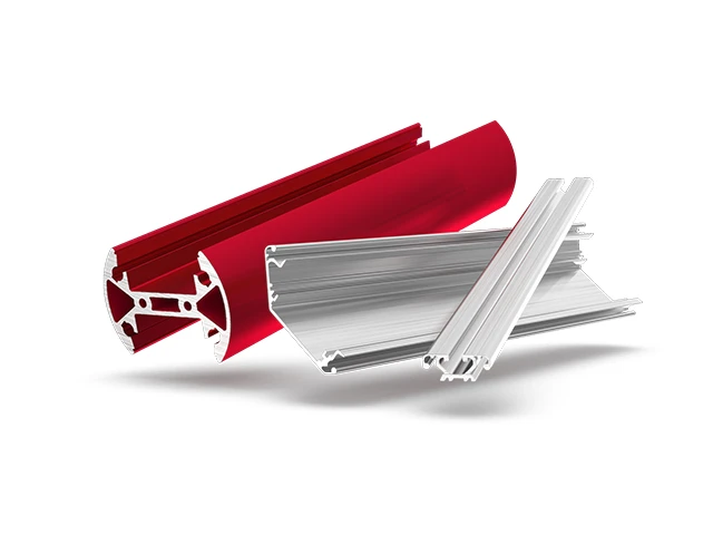
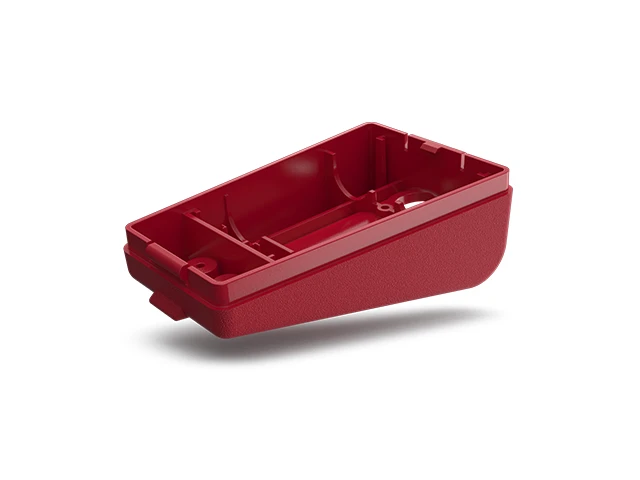
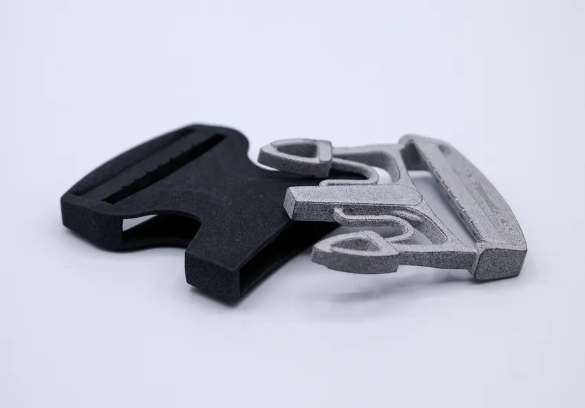
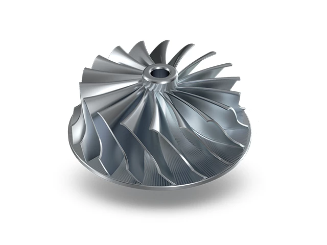
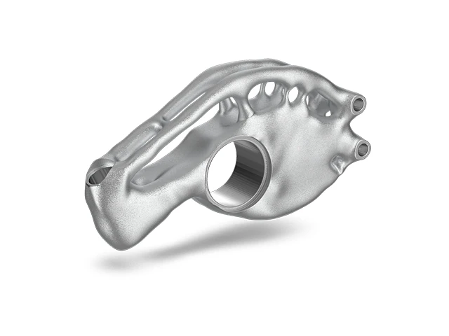
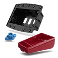
What parts are made using Aluminium Die Casting?
Many parts are manufactured using aluminium die casting. The die casting process can create parts with complex geometries, which makes the process applicable to many industries. Parts made using the die casting technique include:
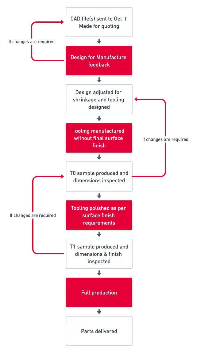
Aluminium Die Casting timeline & trials
The entire project’s aluminium die casting process will often take two months or more from start to completion. Due to the high volume of parts often involved in die casting projects, several trials will be undertaken to ensure the aluminium parts are dimensionally and aesthetically correct before full production. The diagram below outlines a typical timeline for aluminium die casting:
Advantages of Aluminium Die Casting
Aluminium die casting has multiple benefits over other castings, forming and subtractive processes:
✅ Aluminium die-cast parts are lightweight
Aluminium tensile strength properties include a comparably good strength-to-weight ratio. While aluminium might not be suitable for heavy-duty industries such as construction, it is an excellent choice for many other applications.
✅ High volumes can be economically achieved
Due to a short cycle time, minimal material wastage, and high volumes can be produced quickly and cost-effectively.
✅ Excellent corrosion resistance
Cast aluminium alloys do not rust as steel would. Aluminium does oxidise; however, this does not adversely affect the part’s appearance or bulk mechanical properties.
✅ Reduced costs
There is minimal material wastage, so material costs are lower than conventional subtractive processes. Furthermore, labour costs are relatively low due to the short cycle time.
✅ Wide range of surface finishes
Aluminium die-cast parts have many finishing options, including bead blasting, anodising, plating and powder coating. This flexibility allows for a wide range of aesthetic and functional finishes.
Disadvantages of Aluminium Die Casting?
❌ High startup costs
The initial tooling costs are high for die casting as a custom tool has to be CNC machined, which is time-consuming and expensive. However, the part cost is low once the tool has been completed, and the production speed is relatively fast.
❌ Restricted to high-volume production
Due to an expensive tool needing to be manufactured, this manufacturing method is only economical for higher volume production. It is possible to do smaller production runs, but the part cost will be increased.
❌ Complex geometries are expensive
Parts with geometric complexities come at an increased cost as they often require sliding cores and additional machining. See the section below on cost reduction tips to help keep part costs minimum.
❌ Low initial production speed
The tooling has to be machined before any final production parts can be manufactured. This can take some time as alterations to the tooling are often required after the T0 (first run) parts have been reviewed.
Aluminium Die Casting design guidelines
This section will outline some of the key design considerations that should be considered when designing parts for die casting. Following these guidelines will improve the manufacturability of your parts, resulting in higher-quality parts at a lower price.
Die casting draft angles
One of the most critical design features in die casting is adding a draft or draft angle. The draft is the taper applied to the surfaces on the part perpendicular to the parting line and, consequently, on the die cavity. It is vital to include the correct amount of draft. Otherwise, parts can get stuck in the die, causing damage to the part and, worse, the die. It is best practice to consider drafts early in the design process to avoid significant redesign later.
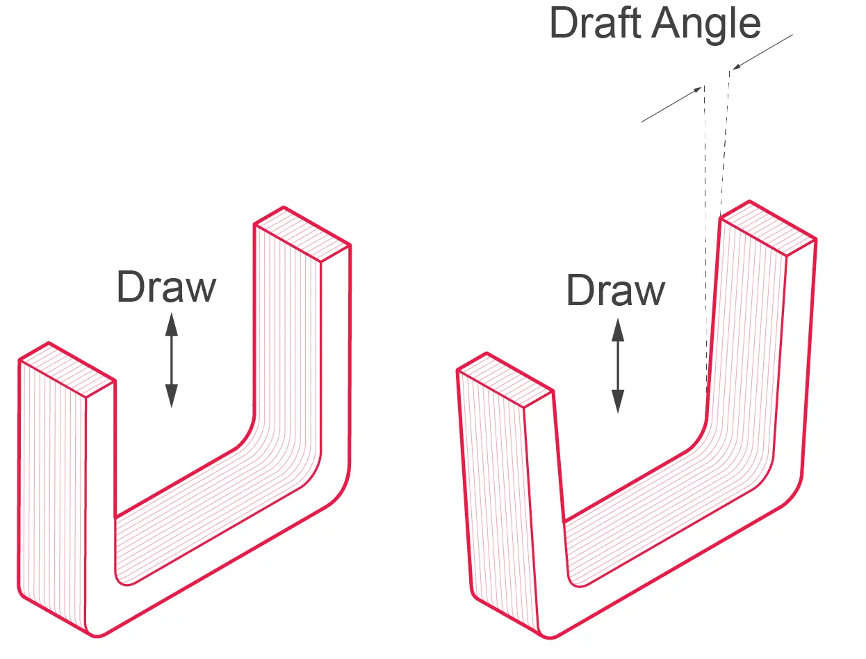
Drafts start on the parting line, and for most geometric features in aluminium die casting, a common draft angle of 2.0 degrees can be applied. The amount of draft will have different calculations depending on whether they are on an inside wall, outside wall or hole.
Draft requirements for inside and outside walls
Draft requirements for cored holes
If you have any questions, speak with a knowledgeable manufacturer to understand the draft required for your parts.
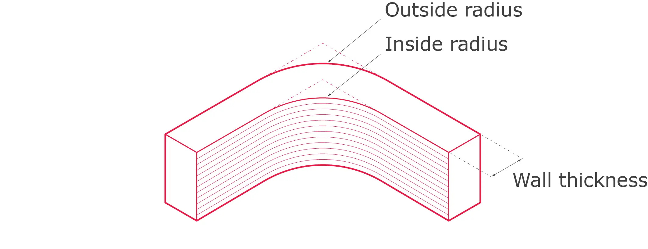
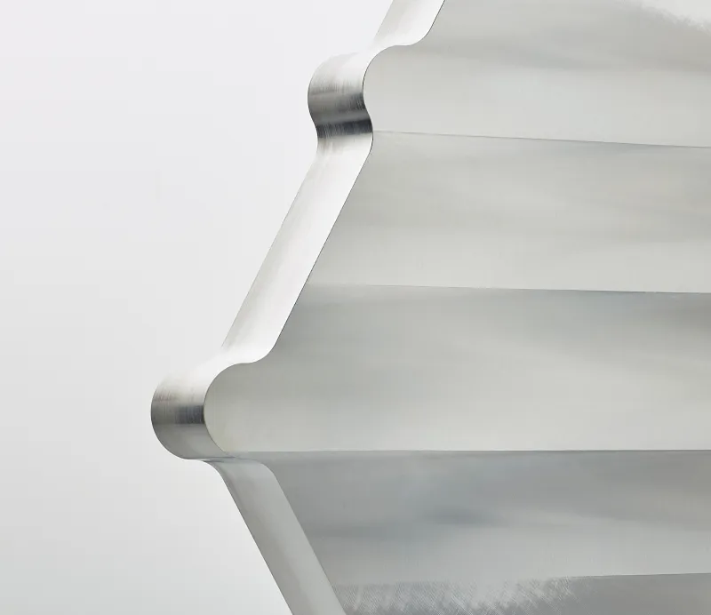
Smooth sharp corners
Sharp corners and edges can be problematic as they create areas of high stress on the part and mould. Therefore, adding the largest feasible fillet to your design is advised to increase the structural integrity of the part and tool life. The metal can flow freely in the mould by smoothly transitioning between surfaces.
- Advised corner radius: 1 mm
- Minimum corner radius: 0.5 mm
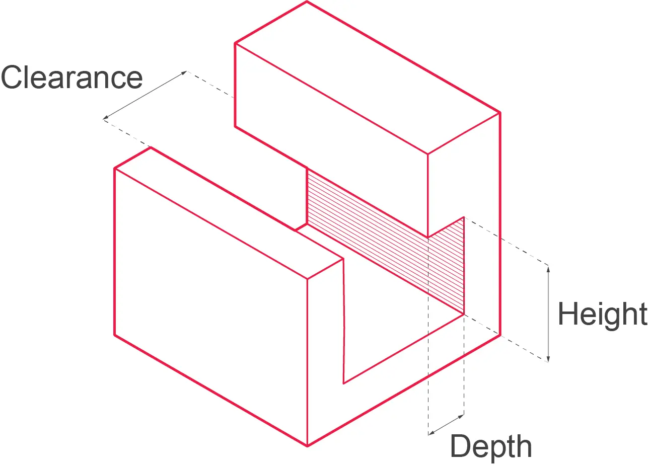
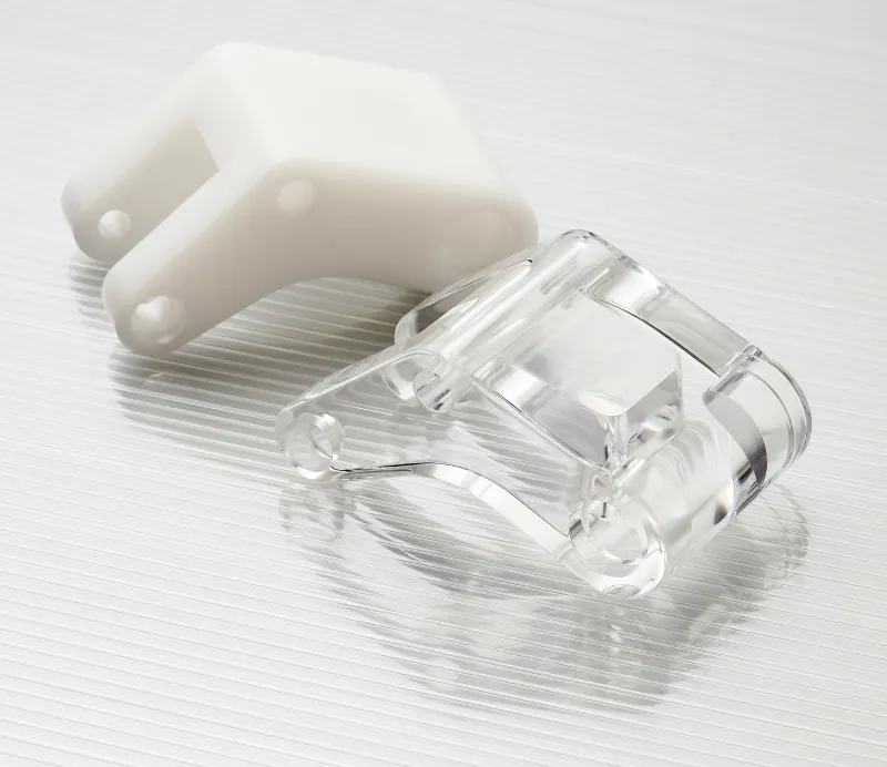
Undercuts
Undercuts are overhanging features that can not be machined with a straight-cutting tool. Try to avoid undercuts and overhangs in your design. However, if these are required, add additional design features, such as slots, to reduce the tooling complexity. If it is impossible to redesign your part to eliminate undercuts sliding cores can be added. Cores are inserts that can slide in and out of the mould to create features such as undercuts. These add complexity and cost to a mould and should be avoided.
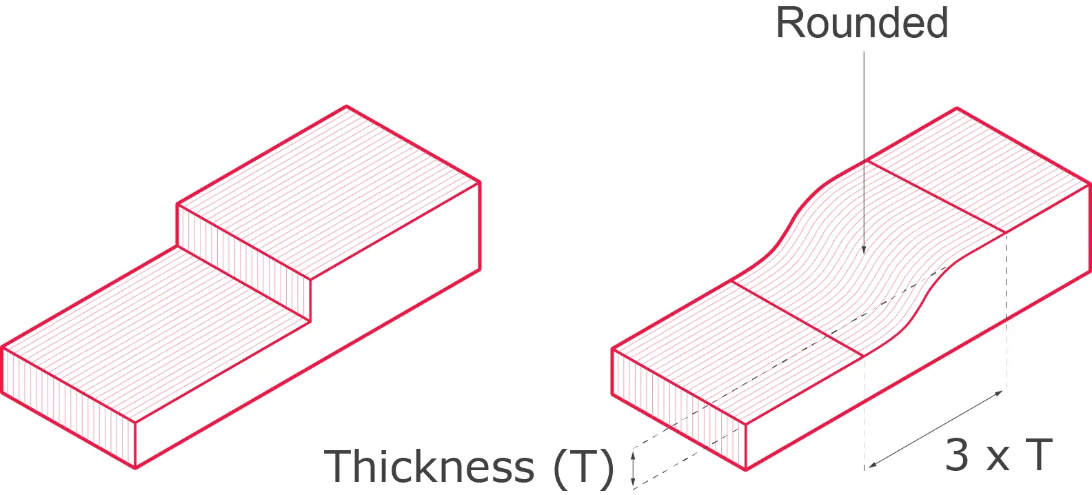
Uniform wall thicknesses
The wall thickness throughout the aluminium material part should be uniform or as consistent as possible. This reduces the chance of distortion when the part cools and shrinks. Furthermore, a constant wall thickness helps to ensure that the die fills evenly. An inconsistent wall thickness can result in cold shuts - a defect whereby the molten aluminium cools and solidifies before filling the mould. If your design contains any thickness changes, try making the transitions as soon as possible, as shown below.
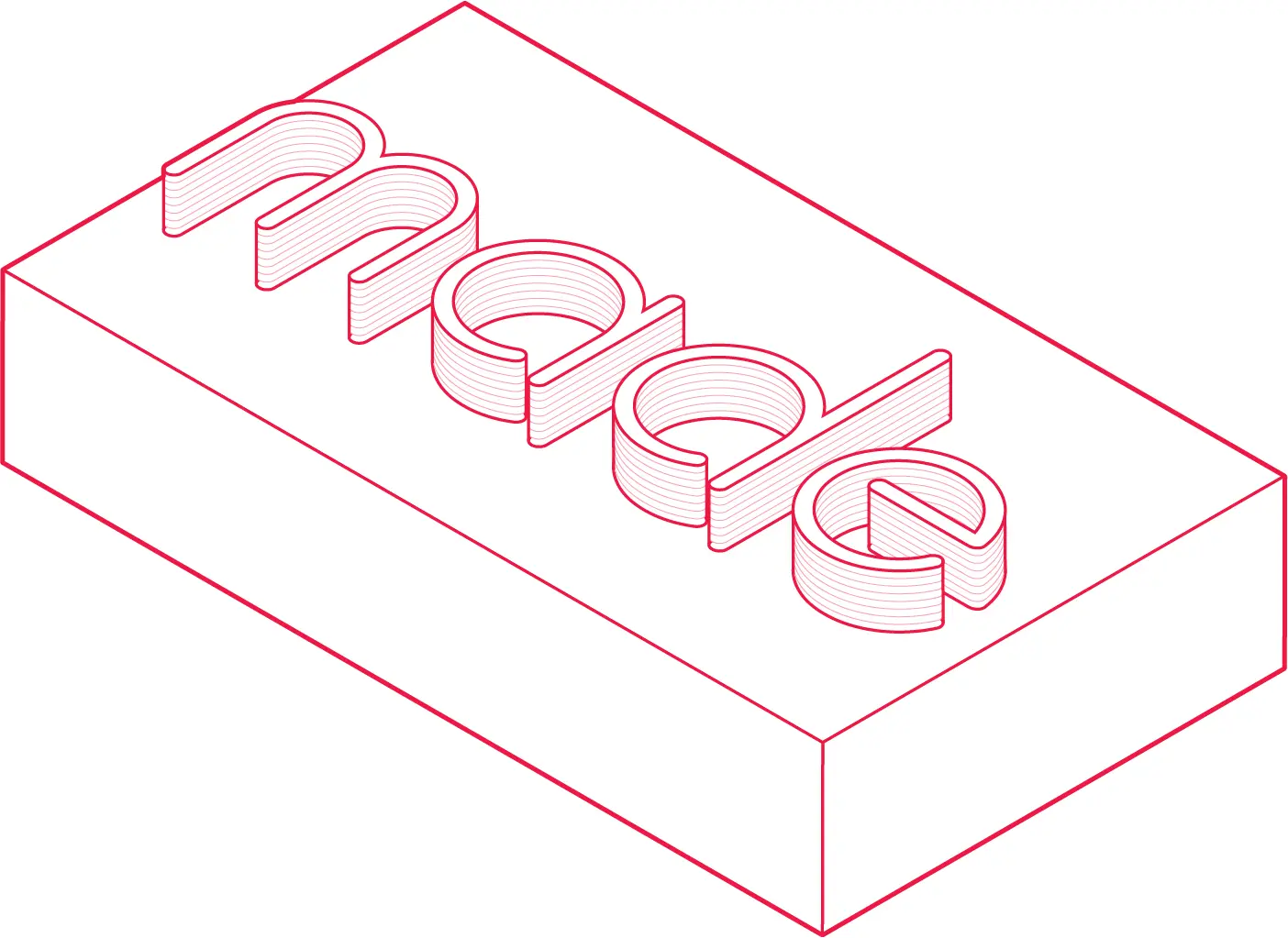
Lettering, symbols and ornamentations
There are two different methods for creating lettering and logos on a die-cast part. The most common and cost-effective way is to use raised (embossed) lettering on the part. This embeds the letters into the cavity, resulting in a longer-lasting imprint. The second technique uses sunk (debossed) lettering on the component through the use of protruding characters in the die. This is more expensive and results in greater wear of the die.
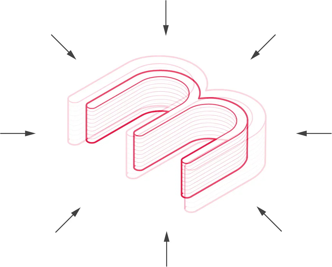
Shrinkage
When the molten metal slows down and cools in the die, the material shrinks. Material shrinkage is unavoidable, so it must be considered when designing the tooling. Thicker sections are more susceptible to shrinkage and, thus internal pores. The designer and manufacturer will design the tooling to evaluate the level of shrinkage. To reduce shrinkage, it is recommended to:
- Avoid large thick sections in your design
- Adding ribs to walls can reduce shrinkage effects
- Squeeze pins can be added to features to reduce the shrinkage porosity
Parting lines
The parting line or plane is where the two die halves split. It is important to determine the location and type of parting line early when designing your parts to avoid any issues arising with undercuts or draft angles. This line's placement mainly depends upon the type of geometrical shape of the part. There are also two parting line choices: a straight parting line or a broken parting line.
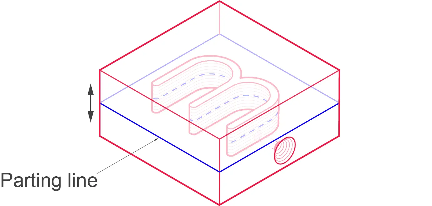
When deciding what type of parting line should be used, a designer should also consider the following:
Die cost - A straight parting line typically lowers the overall tooling cost, but it can be cheaper to design a broken parting line in some instances. This mainly occurs when features within the part require sliding sections, which are typically more expensive than using a breaking line.
Customer specifications - Tolerance limits noted by the designer should be considered. Parting line surfaces usually have a lower-quality finish compared to other surfaces. Whether this is acceptable depends on the type of part or product.
Metal flow - The filling process will depend on the exact placement of the gate inlet, which has to be located in the parting line.
Ejector pins - The faces where ejector pins marks are permissible may influence the location of the parting plane.
Cores - The parting line placement may also be determined by the position of the cores, which are used to form hollow sections in the final part. Cores should be placed in an accessible location close to the parting plane.
Flash - There may be a small amount of excess material formed on the parting line, known as flash. Consider where flash may be acceptable on your parts.
Grades of Aluminium Die Casting
Aluminium alloys are an excellent choice for die casting as they create lightweight parts with a wide range of finishing options. The alloys have excellent corrosion resistance and can make thin-walled parts due to the alloy’s high dimensional stability.
A380
This is the most commonly used grade of aluminium for die casting as it offers the best combination of casting, mechanical strength and thermal properties.

✅ Good castability
✅ Lower cost to other alloys
❌ Not well suited for detailed parts
A383 / ADC12
This grade is often used as an alternative to A380. It has lower levels of copper and higher levels of silicon, making it well-suited for intricate parts with thin walls. It has better corrosion resistance than A380 but is not as good as A413.

✅ Great for intricate parts and thin walls
✅ Increased strength at elevated temperature to A380
❌ Lower tensile strength to A380
A413
This grade offers excellent pressure tightness, which is a good choice for high-pressure applications such as gas cylinders. It is great in high-strength applications and has excellent corrosion resistance due to its lack of iron in the alloy.

✅ Excellent pressure tightness
✅ Excellent mechanical strength
❌ Higher cost to other alloys
❌ High impurities than other alloys
Other die casting materials we offer
Aluminium is the most common material for high-pressure die casting. However, we can also cast Magnesium and Zinc. The table below shows some of the grades we can offer. If you require a specific grade not listed here, please contact us to discuss your requirements.
Surface Finishing
Many post-process surface finishing options are available for die-cast parts, including bead blasting, anodising, plating and powder coating. There are also several 'as cast' finishes which are divided into five classes:
Cost reduction tips for Aluminium Die Casting
This section will outline some of the adjustments that can be made to help reduce the overall cost of your mould and parts. Three main areas will significantly affect the costs:
- Design - Complex designs result in complex and expensive moulds.
- Material - The cost of the bulk material and how easily cast/machined
- Quantity - Cost per unit reduces with an increase in quantity due to fixed setup costs.
Design
Remove Undercuts
Complex tooling with sliding cores or additional machining is required to create an undercut, significantly increasing costs. The design guidelines outlined previously in this guide help demonstrate how slots can be added underneath overhanging features to eliminate the need for sliding cores or additional machining.
Remove Unnecessary Features/Textures
Additional features such as text, company logos and textures will increase overall costs, so avoid them if possible. However, it is best to mould them to prevent other manufacturing processes if they are required. In this case, choosing a simple, easy-to-machine font can help keep costs down. The same applies to adding texture to a part; if required, it is best to mould the texture instead of having an additional finishing step.
Multi cavity Moulds (High volume)
If you require multiple parts of a similar size and the same material, they can be moulded together using a multi-cavity mould. Depending on the size of your part, a tool can contain two up to eight mould cavities. Although the initial tooling costs can appear very high, multiple moulding parts in one go can reduce costs significantly over time.
Optimising Your Design
Part design and, therefore, mould design is vital to the overall cost of a project. Every moulding tool is custom-made, so there are many opportunities to reduce the cost and initial lead time when developing the mould. When optimising a mould to ensure overall efficiency, many nuances take years of experience. This is why it is always recommended to contact a knowledgeable die casting company early in the design process.
Material
The material used in die casting can greatly affect the part cost, so selecting a suitable material depends on its thickness, weight and mechanical requirements is crucial. The cost of a specific material is mainly driven by the price of the bulk material in its raw form. However, how the material interacts with the die can affect the cost of a project. Alloys such as zinc are cast at lower temperatures, meaning they have a longer tool life than magnesium and aluminium alloys. However, aluminium alloys are still the most competitive in price, so it is our most common alloy used when die casting. The mould needs to be manufactured from a harder-wearing material such as tool steel for production, which is an unavoidable cost.
It is advised to select the lowest-cost material with properties that meet your design requirements. If you are unsure about what material to choose, submit a quote with us for a range of materials to give you an idea of the price range.
Quantity
Die casting is best suited for medium to high-volume production. By manufacturing large volumes of parts simultaneously, the fixed costs can be shared across more parts, making each part more economical. For high-volume production, it can be beneficial to create multi-cavity moulds to increase production efficiency. If you go from a one-cavity mould to a four-cavity, you roughly quadruple your production speed while reducing the mould’s wear and tear.
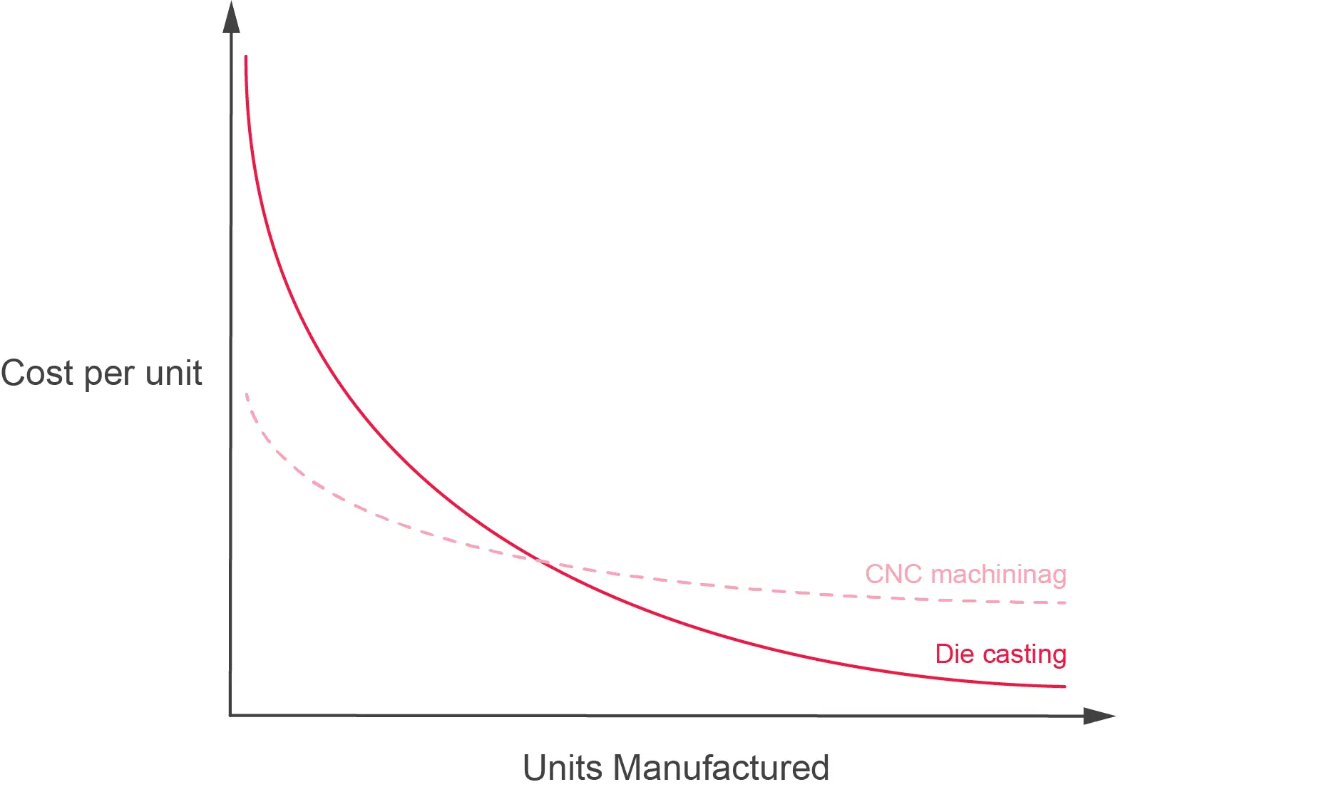
Die casting is an excellent option for medium-high volume production; however, if you are looking at lower volumes, CNC machining and 3D printing become a more cost-effective means of production. See the graph for a visual representation of economies of scale.
How much does die casting cost?
Die casting costs vary considerably based on the required size, complexity, and quantity of parts. The costs can be divided into two main categories: tooling and unit costs. Expect to pay a few thousand pounds at minimum for tooling. However, the price can rapidly increase when incorporating sliding cores, multi-cavity moulds and processes such as EDM. The tooling costs include designing the tool itself, which can be a time-consuming process and manufacturing the metal mould. The great thing about die casting is its speed and efficiency, meaning unit costs can be as little as a few pennies! See how much your die casting project will cost by following the steps below.
Getting Your Part Made
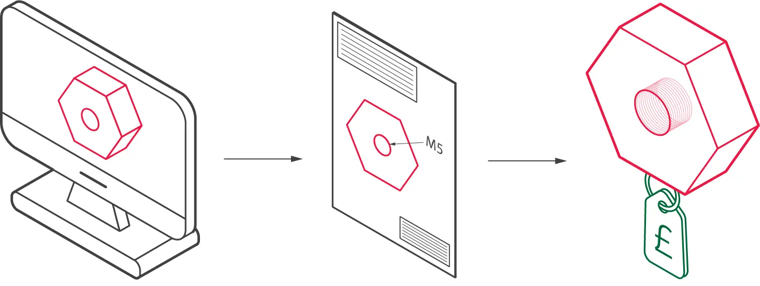
1) Design and export your CAD file
Use the Die Casting Design Guidelines to help design your parts ready for casting and check out our Aluminium die casting service page for more info. Then please export your 3D CAD files to STEP, IGS or PARASOLID format. Unfortunately, we can only accept STL files for 3D printing projects. We cannot accept OBJ files as they do not correct geometric data for manufacturing.
2) Create an engineering drawing
We highly recommend sending supporting PDF engineering drawings for each part. This is required when a part has: thread holes, critical dimensions, tolerances and specific finishing requirements. We can accept an annotated screenshot in some circumstances, such as highlighting a threaded hole. To understand learn how to specify threads, see our threads terminology page, and our metric thread chart.
3) Get a Quote in 24 hours
Please request a free quote today, and one of our engineers will personally review your project within 24 hours. They will then help fine-tune your project to ensure you get the best possible price and lead time for your die-cast parts!
To learn more about the wide range of other manufacturing services offered by Get It Made offers, visit our services.
Leave it to our manufacturing specialists
Get a 24 hour, engineer made quote and design review to start your manufacturing project off on the right foot

Get your production-ready quote in 24 hours
All projects are reviewed by real engineers to ensure accuracy, catch mistakes and unlock DFM improvements
Our services
From 3D printing to CNC machining, we’re experts in manufacturing bespoke precision parts on tight time-frames

Other services
It’s rare you only need CNC machining services. We offer 3D printing, moulding, casting, extrusion, fabrication, assembly, welding & more.
Get your production-ready quote in 24 hours
All projects are reviewed by real engineers to ensure accuracy, catch mistakes and unlock DFM improvements
Working with Get It Made for all our prototyping was an absolute pleasure. Next to immediate response, fast lead times, often arriving before the stated date. Their attention to detail and customer service were second to none. and all at the most competitive price point that could't be beaten in the U.K.

Get It Made are at top of their game when it comes to reliability and quality. We trust Get It Made to deliver parts on time and within tolerance. We can't speak highly enough of their customer service. Get It made are quick to reply to enquiries and keep you well informed throughout the whole process.

Get It Made were able to deliver an accurate and quick service delivering a set of high fidelity prototypes expertly finished, ready for user testing. They offered a range of fabrication options and materials to choose from, tailoring the service to our specific budget, timeframe and material requirements. Can't recommend enough.

Get It Made have over the years been able to take on from simplest to the most complicated of jobs with ease, providing expert advice, good prices and reliable lead times. No job has been too big or too small, either in size or volume. We would strongly recommend Get It Made; you won't be disappointed!

We initially started working with Get It Made, as we needed a high quality product developed within a very short lead time. The entire process went very smoothly and we received the products ahead of schedule. We were pleased with the final results and we found working with Luke very easy, as he offered good technical advice.

When we were looking to have parts manufactured, we had tight deadlines with an even tighter budget. Get It Made understood our constraints and worked with us closely to get our parts to a higher standard than we expected. I can not recommend Get It Made enough. They are professional, communicative, and the parts are fantastic.

The Get It Made team are very responsive and knowledgeable, fully owning a project throughout, providing superb communication. Transparent pricing structure and rapid quotation turnaround is by far the quickest I've experienced, reducing time to manufacture. Get It Made are a pleasure to work with.

Bespoke quote in 24 hours
Get It Made is proud to provide a human service. Get a quote and free design review by an experienced engineer to see how we make manufacturing simple.